
Brazed Plate Heat Exchanger
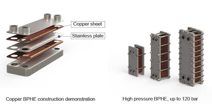
Brazed heat exchanger (BPHE) is a type of compact heat exchanger that consists of corrugated metal plates that are brazed together to form a single unit. The brazing process involves melting a filler material, tipically copper-based alloy (Stainless or Nickle are available) between the plates to create a strong and leak-proof joint.
The main advantages of brazed heat exchangers include their high heat transfer efficiency, compact size, and reliability.
Features :
Compact Size: Brazed heat exchangers corrugated plates create multiple flow channels, maximizing the heat transfer surface area within a small footprint. This makes them ideal for applications where space is limited.
Efficient Heat Transfer: The corrugated plates in a brazed heat exchanger create turbulence in the fluid flow, enhancing heat transfer efficiency. The turbulent flow promotes better mixing of the fluids and minimizes the formation of stagnant zones, leading to improved heat transfer rates.
High Thermal Efficiency: The brazing process used in the construction of these heat exchangers ensures a highly conductive joint between the plates.
Reduced Fouling: The design of brazed heat exchangers with smooth and continuous surfaces minimizes the potential for fouling. The absence of gaskets or crevices reduces the likelihood of accumulation of debris or scale, resulting in lower maintenance requirements and improved overall performance.
Wide Range of Applications:
- HVAC systems
- Refrigeration
- Process cooling
- Industrial heating/ cooling.
- liquid-to-liquid and gas-to-liquid heat transfer processes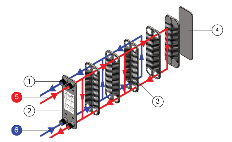
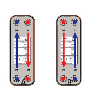
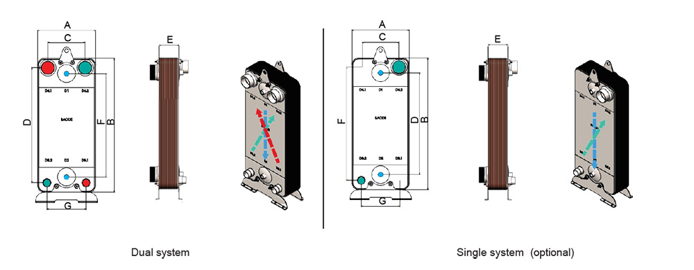
| Flow principle The basic flow principle in a brazed plate heat exchanger is parallel to achieve the most efficient heat transfer process.In a single pass design, all connections are located on one side of the heat exchanger, making installation very easy. The flow principle of a brazed heat exchanger is based on the counter-current flow configuration, where the two fluids involved in the heat transfer process flow in opposite directions. e.g the picture A and B |
 |
Connections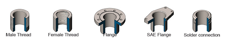
| Material | |
| Cover plates material | 304 stainless |
| Flow plates |
316L/304 stainless |
| Connections | 304 stainless |
| Brazing material |
Copper / Ni / Stainless |
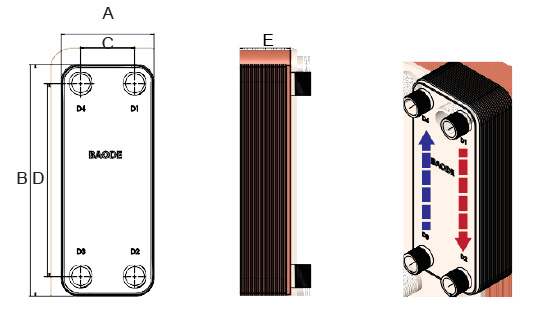
Single circuit BPHE data (unit: mm)
|
Model |
Design Pressure |
A |
B |
C |
D |
E |
Chinnel Volume L |
|
BL6 |
30/45 |
55 |
119 |
26 |
91 |
7+1.29N |
0.0053 |
|
BL12 |
30/45 |
76 |
152 |
42 |
120 |
7+1.29N |
0.01 |
|
BL13 |
30/45 |
76.5 |
194 |
40 |
154 |
8+1.05N |
0.0093 |
|
BL14 |
30/45 |
76 |
206 |
42 |
172 |
8.6+2.3N |
0.027 |
|
BL14D |
10 |
71 |
186 |
40 |
154 |
7.5+2.26N |
0.026 |
|
BL15A |
10 |
83 |
193 |
40 |
154 |
7+2.26N |
0.029 |
|
BL14W |
30/45 |
78 |
206 |
42 |
172 |
7.5+2.26N |
0.028 |
|
BL16 |
30/45 |
78 |
206 |
42 |
172 |
7.5+2.26N |
0.028 |
|
BL17 |
30 |
85 |
202 |
39 |
153 |
24.5+2.31N |
0.031 |
|
BL18 |
10 |
91 |
210 |
50 |
162 |
9+3.3N |
0.053 |
|
BL20 |
30/45 |
77 |
317 |
42 |
282 |
8+2.31N |
0.042 |
|
BL20W |
30/45 |
75 |
315 |
42 |
282 |
11+2.25N |
0.042 |
|
BL21 |
45 |
76 |
312 |
42 |
278 |
6.6+1.23N |
0.021 |
|
BL25 |
30/45 |
92 |
322 |
39 |
268 |
8+1.55N |
0.032 |
|
BL26 |
30/45 |
109 |
310 |
50 |
250 |
10.6+2.35N |
0.057 |
|
BL26W |
30/45 |
106 |
306 |
50 |
250 |
10.9+2.25N |
0.057 |
|
BL30 |
30/45 |
124 |
304 |
70 |
250 |
12+2.31N |
0.069 |
|
BL50 |
30/45 |
108 |
525 |
50 |
466 |
9.5+2.31N |
0.097 |
|
BL60 |
30/45 |
119 |
526 |
63 |
470 |
9.4+2.31N |
0.11 |
|
BL95A |
30/45 |
187 |
616 |
92 |
519 |
10.2+2.31N |
0.2 |
|
BL95B |
30/45 |
187 |
616 |
92 |
519 |
11+2.81N |
0.25 |
|
BL95C |
30/45 |
187 |
616 |
92 |
519 |
11+2.81N |
0.25 |
|
BL120 |
30/45 |
245 |
529 |
174 |
456 |
12.4+2.31N |
0.24 |
|
BL122 |
30/45 |
246 |
529 |
174 |
456 |
12.4+2.31N |
0.24 |
|
BL125 |
30 |
248 |
530 |
159 |
441 |
12+1.95N |
0.2 |
|
BL180 |
30/45 |
256 |
846 |
160 |
750 |
8+2.31N |
0.4 |
|
BL190 |
15/21/30 |
307 |
698 |
179 |
567 |
9+2.81N |
0.49 |
|
BL195 |
15/21/30 |
306 |
694 |
179 |
567 |
11.2.31N |
0.39 |
|
BL200 |
15/21/30 |
320 |
740 |
188 |
603 |
12+2.75N |
0.54 |
|
BL350 |
30 |
304 |
981 |
179 |
854 |
11.5+2.31N |
0.55 |
|
BL600 |
15/21 |
436 |
140 |
220 |
1190 |
16.3+2.8N |
1.4 |
|
Model |
Design Pressure (bar) |
A |
B |
C |
D |
F |
E |
Channel Volume L |
|
BL100 |
30/45 |
248 |
496 |
405 |
157 |
405 |
7+1.29N |
0.2 |
|
BL100E |
30/45 |
248 |
495 |
411 |
159 |
369 |
10+2.09N |
0.2 |
|
BL100EW |
30/45 |
243 |
491 |
411 |
159 |
369 |
10+2.03N |
0.2 |
|
BL130AS |
45 |
293 |
532 |
397 |
177 |
399 |
12.3+2.05N |
0.27/0.24 |
|
BL210 |
30/45 |
320 |
737 |
568 |
205 |
631 |
8+2.61N |
0.5 |
A dual system BPHE (Brazed Plate Heat Exchanger) refers to a brazed plate heat exchanger that is specifically designed to accommodate two separate and independent fluid circuits within a single compact unit. It consists of two separate sets of plates, each forming a distinct flow path for a different fluid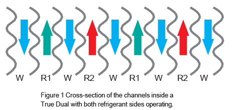
Part-load efficiency also decreases with these arrangements, because the flow arrangement means that only 50% of the secondary fluid undergoes heat exchange. The evaporation temperature at part load may therefore decrease, reducing system efficiency and increasing the risk of freezing. Instead, True Dual technology BPHEs have two independent refrigerant circuits combined with a common secondary fluid circuit. A True Dual heat exchanger is shown in Figure 1.
A True Dual BPHE running with both circuits active operates no differently from a high-efficiency single circuit evaporator with full contact between refrigerant and secondary fluid.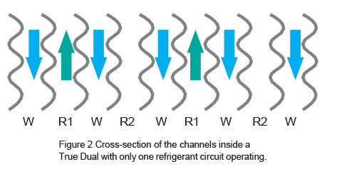
Even if one refrigerant circuit is closed, i.e. half-load operation, all secondary fluid channels remain in contact with the active refrigerant channel (see Figure.2). All the secondary fluid will still receive heat exchange, and the leaving water temperature will therefore be the same as for full-load operation provided the water flow is also halved. This allows the part-load evaporation temperature to remain at a high level, resulting in increased efficiency at part load. Because secondary fluid channels will surround the active refrigerant circuit, the evaporating process will also remain fully stable.
For a schematic system sketch of a True Dual system, see Figure 3.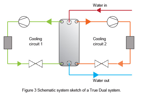
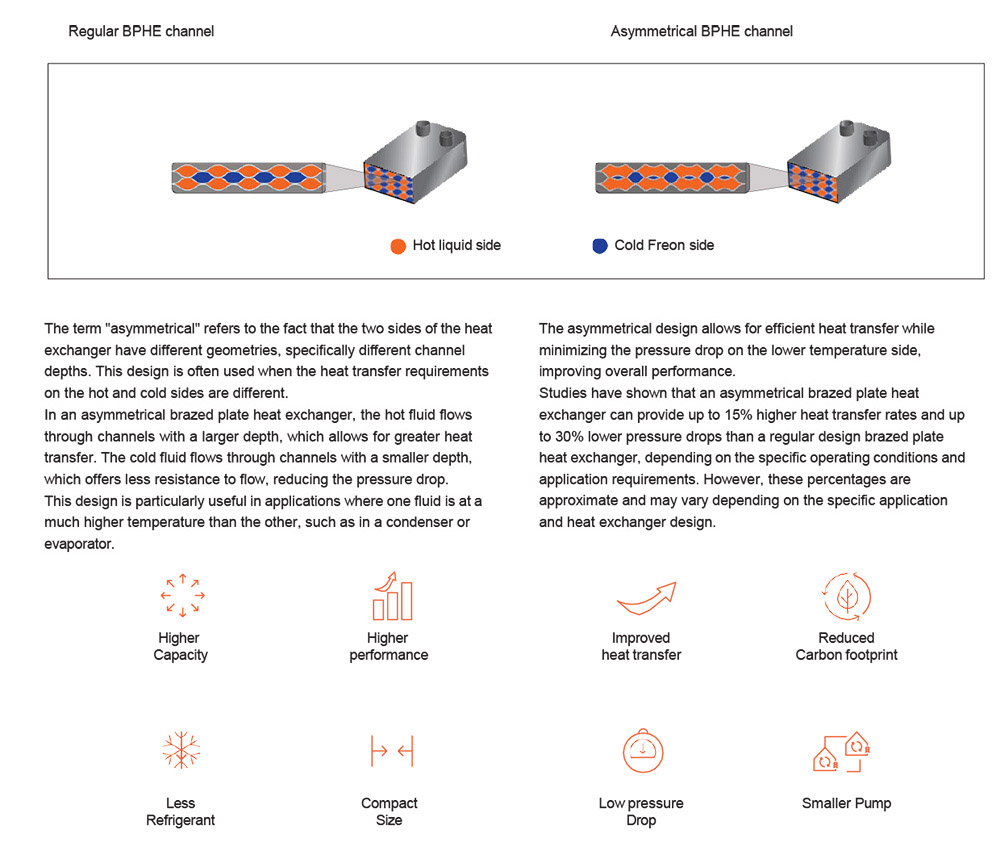
Asymmetrical brazed plate heat exchanger.
|
Model |
Design Pressure |
A |
B |
C |
D |
E |
Channel Volume L |
|
BL37AS |
30/45 |
121 |
332 |
68 |
279 |
11.3+1.55N |
0.05/0.04 |
|
BL40AS |
30/45 |
119 |
376 |
72 |
329 |
12+1.55N |
0.044/0.066 |
|
BL61AS |
30/45 |
118 |
524 |
63 |
470 |
10.5+1.91N |
0.092/0.075 |
|
BL95AS |
30 |
185 |
613 |
92 |
519 |
11.3+2.07N |
0.2/0.16 |
|
BL150AS |
21/30 |
266 |
696 |
122/131 |
564/545 |
10+2.31N |
0.36/0.3 |


